Índice:
- Autor John Day day@howwhatproduce.com.
- Public 2024-01-30 11:39.
- Última modificação 2025-01-23 15:03.
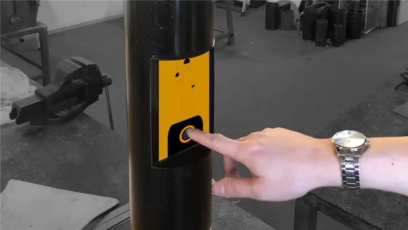
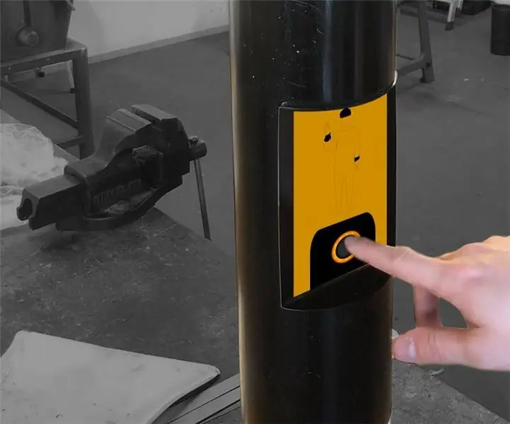
Pronto para construir o melhor e mais interativo semáforo do mundo? Boa! Neste tutorial, explicaremos como você pode construir um sozinho usando o Arduino.
Componentes necessários: - Arduino (..duh) - LM317 Mosfet - Tiras de LED RGB analógico 2x 60cm (12V) - Tubo de PVC (1m x 125mm) - Cabos (vermelho e preto) - Placas de metal para capas de luz - Acril para a luz -icons (verifique flaticon.com para ícones.svg) - Tinta spraycan preto e branco.- Fita isolante- Todos os componentes de soldagem necessários- Visor com proteção necessária (não usado no tutorial)
Etapa 1: Etapa 1: fazer as capas luminosas
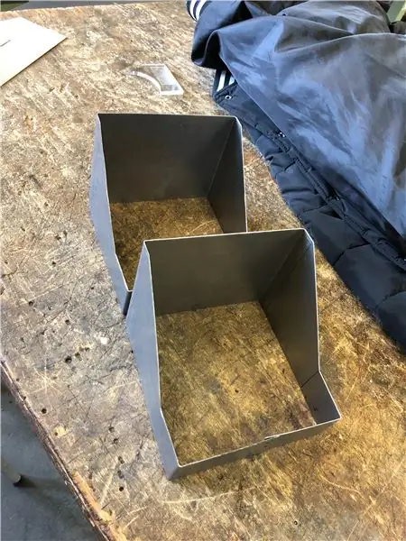
O design é realmente com você. Fizemos uma tampa de 15x15cm para segurar as luzes. Cortamos as placas de metal no tamanho correto e usamos um dobrador de metal (não, não do Avatar) para dobrar as tampas nas formas corretas. As placas traseiras foram feitas de um componente diferente.
Etapa 2: Etapa 2: Preparação do poste de PVC
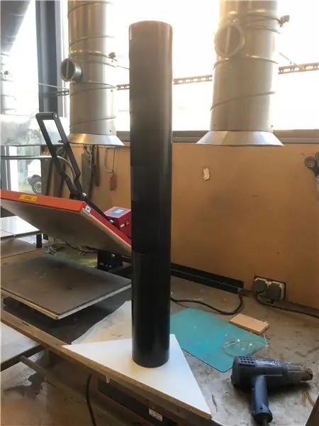
Faça 2 furos no poste de PVC para encaixar as capas de luz. Em seguida, use uma lata de spray de tinta preta para pintar tudo de preto. Se desejar, você pode adicionar listras brancas na parte inferior do mastro (comum na Holanda).
Etapa 3: Etapa 3: montagem das tiras de LED RGB e jato de areia das placas de acrílico
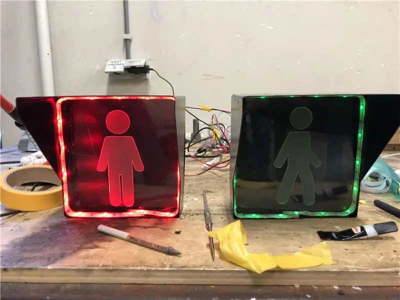
Em seguida, você precisará montar as tiras de LED RGB dentro da tampa de luz. Ajuste-os firmemente ao redor da tampa e coloque-os o mais próximo possível da frente.
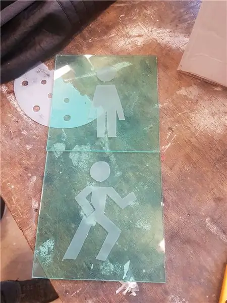
Em seguida, você precisará jatear o símbolo selecionado para na placa de acrílico. Pegue um pouco de fita e cubra toda a placa de acrílico. Em seguida, corte a forma / figura que você deseja. Depois disso, você pode jatear a placa para obter um efeito de vidro fosco.
Etapa 4: Etapa 4: conectar as tiras de LED RGB ao Arduino
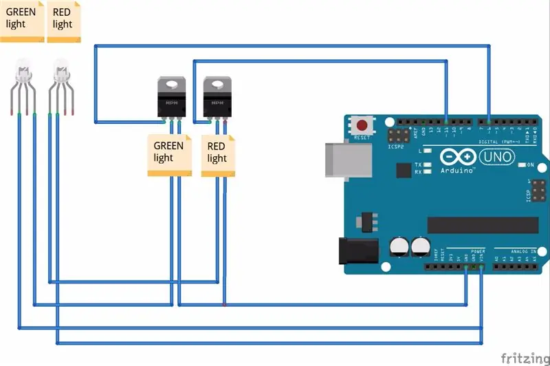
Agora vem a parte complicada: conectar as fitas de LED RGB ao Arduino. Ao conectar os pinos certifique-se de colocar 12v nos 12v da sua tira. Entre cada cor, seja vermelha ou verde, você precisa colocar um mosfet. Conecte os dados da faixa de led ao pino do meio do mosfet e o pino esquerdo ao seu Arduino. O pino certo deve voltar ao solo do Arduino.
Etapa 5: Etapa 5: escrever o código do Arduino
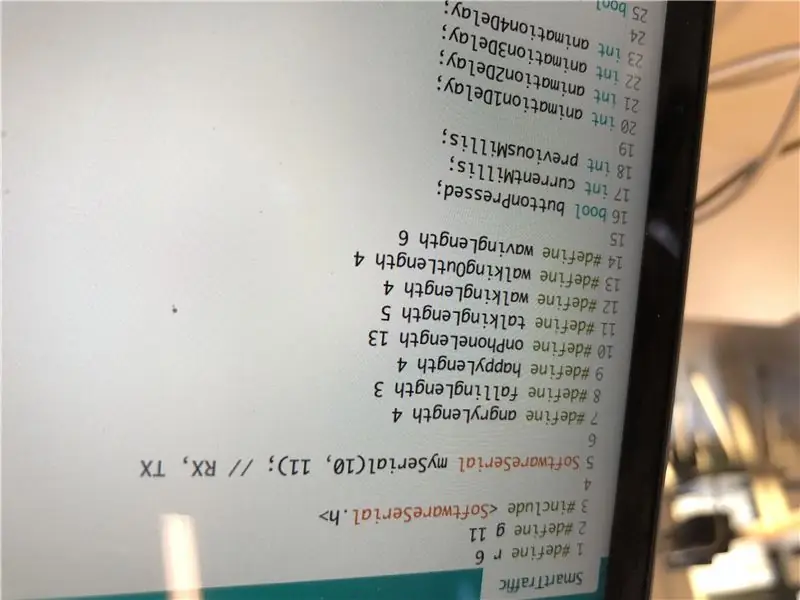
Este código do Arduino é controlado por bluetooth, pois não usamos um display interno. Portanto, o código é controlado por meio de mensagens bluetooth na função loop ().
#define r 6 # define g 11 #include
SoftwareSerial mySerial (10, 11); // RX, TX
#define angryLength 4
#define fallingLength 3 #define happyLength 4 #define onPhoneLength 13 #define talkingLength 5 #define walkingLength 4 #define walkingOutLength 4 #define wavesLength 6
bool buttonPressed;
int currentMillis; int previousMillis;
int animation1Delay;
int animation2Delay; int animation3Delay; int animation4Delay;
bool animation1Done = false;
bool animation2Done = false; bool animation3Done = false; bool animation4Done = false; bool animation5Done = false;
bool blockLight = false;
bool lightRed = true;
int currentAnimationDelay;
void setup () {
// coloque seu código de configuração aqui, para executar uma vez: pinMode (r, OUTPUT); pinMode (g, OUTPUT);
Serial.begin (9600);
mySerial.begin (38400); Serial.setTimeout (25); buttonPressed = false; currentMillis = 0; anteriorMillis = 0;
animation1Delay = walkingLength * 1000;
animation2Delay = wavesLength * 1000; animation3Delay = happyLength * 1000; animation4Delay = walkingOutLength * 1000;
// currentAnimationDelay = animation1Delay * 1000;
lightRed = true; }
void loop () {
// atraso (20);
// coloque seu código principal aqui, para executar repetidamente: unsigned long currentMillis = millis (); if (buttonPressed == true) {if (animation1Done == false) {if (currentMillis - previousMillis> animation1Delay) {Serial.println ("0"); anteriorMillis = currentMillis; animation1Done = true; }} else if (animation2Done == false and animation1Done == true) {if (currentMillis - previousMillis> animation2Delay) {Serial.println ("1"); anteriorMillis = currentMillis; animation2Done = true; }} else if (animation3Done == false and animation2Done == true) {if (currentMillis - previousMillis> animation3Delay) {Serial.println ("2"); //Serial.println("sound:green "); anteriorMillis = currentMillis; animation3Done = true; lightRed = false; }} else if (animation4Done == false and animation3Done == true) {if (currentMillis - previousMillis> animation4Delay) {previousMillis = currentMillis; animation4Done = true; Serial.println ("FLSH"); }}}
if (Serial.available ()) {
String str = Serial.readString (); if (str == "CMD: BUTTON_PRESSED") {
animation1Done = false;
animation2Done = false; animation3Done = false; animation4Done = false; animation5Done = false;
animation1Delay = walkingLength * 1000;
animation2Delay = wavesLength * 1000; animation3Delay = happyLength * 1000; animation4Delay = walkingOutLength * 1000;
// currentAnimationDelay = animation1Delay * 1000;
lightRed = true; Serial.println ("3"); buttonPressed = true; anteriorMillis = currentMillis; }
if (str == "RED") {
blockLight = false; lightRed = true; }
if (str == "VERDE") {
blockLight = false; lightRed = false; }
if (str == "LUZ: VERDE: DESLIGADO") {
blockLight = true; analogWrite (g, 255); } if (str == "LIGHT: GREEN: ON") {blockLight = true; analogWrite (g, 0); } //Serial.println(str); }
if (blockLight == false) {
if (lightRed == true) {
analogWrite (r, 0); analogWrite (g, 255); } if (lightRed == false) {analogWrite (r, 255); analogWrite (g, 0); }}}
Recomendado:
BBC Micro: bit and Scratch - Volante interativo e jogo de direção: 5 etapas (com imagens)

BBC Micro: bit and Scratch - Volante interativo e jogo de direção: Uma das minhas tarefas de aula esta semana é usar o BBC Micro: bit para fazer a interface com um programa Scratch que escrevemos. Achei que essa era a oportunidade perfeita para usar meu ThreadBoard para criar um sistema embarcado! Minha inspiração para o scratch p
Despertador inteligente: um despertador inteligente feito com Raspberry Pi: 10 etapas (com imagens)
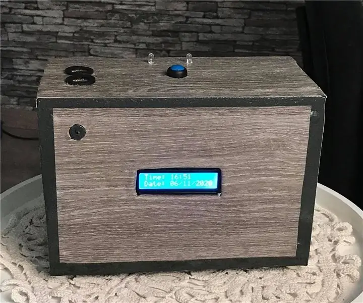
Despertador inteligente: um despertador inteligente feito com Raspberry Pi: Você sempre quis um relógio inteligente? Se sim, esta é a solução para você! Fiz o Smart Alarm Clock, é um relógio que você pode alterar a hora do alarme de acordo com o site. Quando o alarme disparar, haverá um som (campainha) e 2 luzes
Minecraft interativo não entra em espada / sinal (ESP32-CAM): 15 etapas (com imagens)
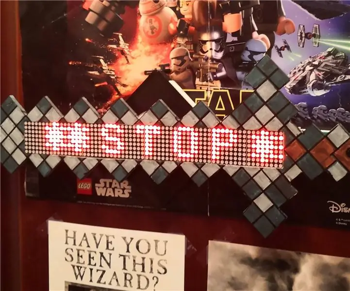
Minecraft interativo não entra em espada / sinal (ESP32-CAM): Existem realmente vários motivos pelos quais este projeto surgiu: 1. Como autor da biblioteca multitarefa cooperativa TaskScheduler, sempre tive curiosidade em saber como combinar os benefícios da multitarefa cooperativa com os benefícios da preventiva
Gerador de folha a laser interativo com Arduino: 11 etapas (com imagens)
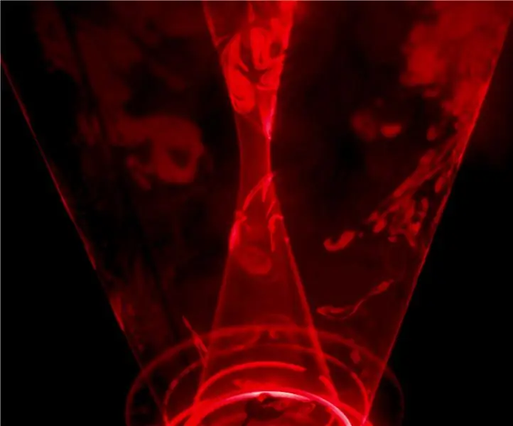
Gerador de folha de laser interativo com Arduino: Os lasers podem ser usados para criar efeitos visuais incríveis. Neste projeto, construí um novo tipo de display a laser que é interativo e toca música. O dispositivo gira dois lasers para formar duas folhas de luz semelhantes a vórtices. Incluí sensor de distância
Espelho infinito interativo: 9 etapas (com imagens)
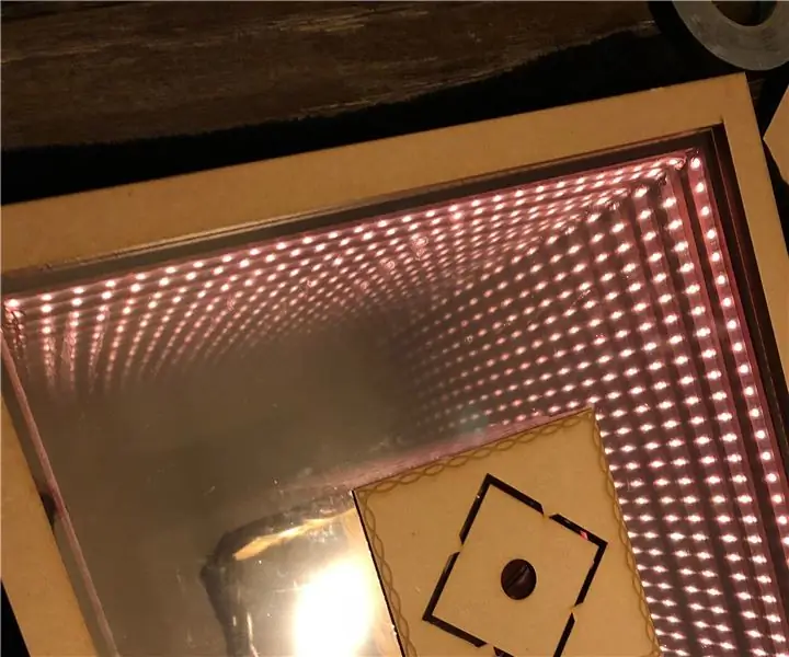
Espelho Infinito Interativo: A tarefa para esta classe era simples, mas complicada: Faça algo interativo com um Arduino. Ele tinha que ser bem projetado, tecnicamente desafiador o suficiente e original para as idéias originais hoje em dia em sites como o Instructables. Para
